1. Planning of GPS observation
Before starting a GPS Survey Campaign, the following points should be kept in mind.
1.1. Pre Survey planning:-
- A satellite “sky plot” or visibility chart should be prepared for each site.
- Observation time is decided when the satellite visibility is maximum and pdop is minimum.
1.2. Selection of site
The possible locations of GPS control points to be established are selected on map. Starting and closing GT station are also selected. While selecting the station the following points should be kept in mind:
- Distance between two stations should not be large and should be kept within 50km. As far as possible.
- Since inter-visibility between the station is not required, the station with easier approach should be selected for speed and economy.
- A 15degree clearance from horizon to sky should be available. Where 15 degree clearance is not possible due to fixed location of points, GPS mission planning should be done in the office to select the right time of observation, to ensure maximum satellite visibility.
- No radio signal transmitter should be operational in the vicinity of the GPS point.
- The point selected should be such that it is not likely to be destroyed due to human activities like construction etc. In case the requirement of control points is of the temporary nature like for model control etc. few points at sufficient density should be selected which can be used as permanent control points for mapping and these should be constructed as per standard of GT station.
- Stations near H. T. power lines should be avoided.
1.2. Field Procedure
The GPS observation will yield coordinates of the survey stations in the World Geodetic System WGS-84 , which is a geocentric datum. These coordinates are not very precise and accurate due to effect of SA and AS and even if we get accurate coordinates from GPS we can not use the coordinates as it is. Because our reference system is Everest Ellipsoid which is totally different from WGS-84.
However for precise work, GPS can be very effectively used in static relative mode (translocation mode), by using two or more receivers observing simultaneously at different locations. In this mode due to cancellation of major part of SA effect the base lines can be estimated very accurately. This is the method being employed for all geodetic and topographical surveying with GPS in Survey Of India.
The basic observable in the planimetric GPS observation is the base line vector between stations. To derive the coordinates on Indian Geodetic Datum – the Everest Ellipsoid, the observations are started and closed on existing Geodetic Stations of the Great Trigonametrical (GT) triangulation network, whose coordinates on the Everest Ellipsoid are known.
The distances observed with GPS observation (after data processing we get slope distance) are projected on the Everest Ellipsoid using computed ellipsoidal heights and final network adjustment is carried out using the coordinates of known stations and the GPS derived base line vectors projected on Everest ellipsoid. For computation of height Bench Marks of existing H.P. / Precision / Secondary or tertiary levelling are connected with GPS network at regular interval.
In case of vertical control, the basic observable is the MSL heights (orthometric heights) derived from ellipsoidal heights obtained from GPS observation, by applying Geoid – Ellipsoid separation (N). By using known MSL height of BM, and these height differences, the heights of GPS stations are derived.
1.3. Observation Procedure
The procedure to be followed for GPS observations will be depend on the type of GPS receiver being used and the accuracy required. Mainly two types of GPS receiver have been used in Survey of India.
For primary Geodetic Control work, GPS observations for about 2 to 4 hours with proper Observation Procedure for base line of the order of 20 to 40 km are found to be sufficient. For topographical survey and short base lines about 30 minutes observation should be sufficient. The recording interval should be 30 seconds.
For special type of surveys like Crustal movement studies and for long base lines of hundreds of kilometres, long observations are required. In G&RB Survey of India for such type of work 24 hours observations are carried out.
A site chart containing a description of the site, sketch of site, weather data and any other information relevant to the observations is prepared at the time of taking the observations.
1.4. Data Downloading and Processing
After the receiver have collected the field data, the receivers are connected to the computer using a data downloading cable (RS232) and the data is downloaded into the computer for post processing with the help of downloading software provided with each instrument.
After downloading, the data processing is done with the help of different software supplied with the different receiver e.g.
Ashtech Processing and downloading software Prism or GPPS
Leica Processing and downloading software SKI
Trimble Processing and downloading software Gpsurvey
WM102/101 Processing and downloading software Pops
There is scientific software developed by University of Berne named BERNES is the best among the above. BERNES software can process data collected by any receiver, it is more powerful, scientific and gives more precise results.
In BERNES software additional information can be used which can not be used with other software. For example to achieve higher accuracy the following files can be downloaded from internet and can be used during processing.
POLE file or ERP file – contain the Earth Rotation Parameters.
PHASE IGS file – contain the different receivers and antenna pair parameters. For processing in BERNES data in RINEX format is required.
1.5. What is RINEX format?
RINEX stands for RECEIVER INDEPENDENT EXCHANGE
Each receiver type has its own binary data format. As a consequence, data of different receiver type can not easily be processed simultaneously with one particular GPS data processing software package.
To solve this problem, either all manufacturer has to use the same data output format, or a common data format has to be defined that can be used as a data interface between all geodetic receiver type and different processing software system.
Based on development at the University of Berne the Receiver Independent Exchange format was proposed by Grutner at the fifth international geodetic symposium on satellite positioning. RINEX has been accepted by international user community and by the community of the receiver manufacturers. For most of the geodetic receivers the translator software is provided by the manufacturer that converts the receiver dependent data into RINEX format. On the other hand, all major data processing software requires RINEX data as input like BERNES software. RINEX hence serve a general interface between receivers and multipurpose data processing software.
RINEX format consists of 3 ASCII files
- Observation data file contain header information and phase and range data.
- Navigation file contain ephemeris data
- Meteorological file contain Meteorological data
The file names are as follows:
00010731.02O / n / m
0001 stands for point ID No.
073 stands for Julian day
1 stands for session No.
02 stands for year
O stands for observation / n for navigation etc.
1.6. Steps Involving to get Everest coordinates of unknown site OR Adjustment of data
After processing we get the following results
- Latitude, Longitude and ellipsoidal height of stations with respect to WGS-84 datum.
- Slope distance or baseline vector between the stations.
- X, Y, Z coordinates with respect to ECEF system.
- Azimuth of the baseline vector.
The coordinates obtained after processing are of no use as they are on WGS-84 reference system while our reference system is Everest. Therefore we in Survey of India use only baseline vectors. The adjustment carried out as follows
1.6.1. Height Adjustment
As we need ellipsoidal height of the stations for reducing slope distances on the Everest ellipsoid, first of all the height adjustment is to be carried out.
Data required for height adjustment:-
- Dh – The ellipsoidal height difference of each baseline vector obtained from Ellipsoidal Height (above WGS-84) of stations.
- Baseline length of all measured baselines in km.
- N – The geoidal undulation or separation between Geoid and Everest ellipsoid.
- Height of at least one Bench Mark which is connected with GPS network.
1.6.2. How the Orthometric heights of stations deduced from known BM height?
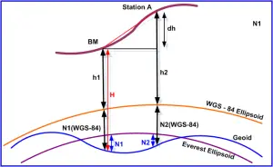
Figure 1: Orthometric Height Calculation
Let the Orthometric of BM = H
Ellipsoidal Height of BM above WGS-84 = h1
Ellipsoidal Height of Station A above WGS-84 = h2
E – Height difference Between BM and Station A= h2 – h1 = Dh (Ellipsoidal Height difference)
Geoidal Undulation at BM = N1 (Between Geoid and Everest Ellipsoid)
Geoidal Undulation at Station A = N2 (Between Geoid and Everest Ellipsoid)
Ellipsoidal Height of BM above Everest = H – N1 = h (say)
Ellipsoidal Height of Station A above Everest = h + Dh = hA (say)
Orthometric Height of Station A = = hA + N2 = HA (say)
The program SOILAP is used for height adjustment.
1.6.3. Reduction of Slope Distances on Everest Ellipsoid
For reducing slope distances on Everest Ellipsoid Program SLARC is used. The following input data is required-
- Observed Slope distances
- Height of stations (if orthometric then value of N also)
- Latitude of stations
- Azimuth of each baseline
1.6.4. Adjustment of Network
To adjust the complete network, the program SOITAP is used which is based on variation of coordinate method. The input data required for the program is
- Reduced distances on Everest ellipsoid
- Provisional coordinates of each station
- Geodetic coordinates of known stations (if only one station is known, then azimuth of a baseline connected to the known station is also required).
1.6.5. Mathematical Formulae involved in computation of Geodetic Coordinates
Step 1:- First of all the heights of all the points adjusted as per triangulation
- Find dh of all observed vectors. (dh = hA – hB )
- Make a observation chart and calculate height misclosure of each triangle in the network.
- If there is any discrepancy adjust it as proportional to vector distance.
- Compiled geoidal undulation (N) of each station from the geoidal undulation chart. This chart is available in Geodetic & Research Branch, Dehra Dun and they supply value of N on the basis of Latitude and Longitude of the stations.
- Convert the orthometric height of known station to ellipsoidal height above Everest ellipsoid by using the formula h =H + N.
- On adding the adjusted dh with h we can get the ellipsoidal height of each station.
- The ellipsoidal height is used for reducing the slope distance to arc distance in the next step.
- Find orthometric height of each station using the formula H = h – N.
Step 2:- Reduction of observed slope distances on Everest ellipsoid
Reductions of a spatial distance on Ellipsoid:-

Figure 2: Slope Distance Reduction
By cosine formula we have
l2 =(R +hA)2 + (R+hB)2 – 2(R+hA)(R+hB)cosy
l2 = (R +hA)2 + (R+hB)2 – 2(R+hA)(R+hB){1-2sin2(y/2)}
l2 = {(R +hA) – (R+hB)}2 + 4 (R+hA)(R+hB) sin2(y/2)
l2 = (hA – hB )2 + 4R2(1 + hA/R) (1+hB/R) sin2(y/2)
From this equation we can find y
Now So = Ry (y in Radian)
Another formula can also used to reduced slope distances in to arc distances is –
(Form – 3 Tellumach of Survey of India)
= Chord Distance
= correction to convert chord distance in to arc distance
Arc distance = X + Y
d – Slope distance between station A and B
hA – Ellipsoidal height of station A
hB – Ellipsoidal height of station B
dh = hA ~ hB
R = Mean radius of curvature of Earth for the section AB.
Where a is the azimuth of the baseline AB
r = a (1-e2) / (1-e2Sin2fm)3/2 =Radius of curvature of meridonial section
u = a / (1-e2Sin2fm)1/2 = Radius of curvature of Prime Vertical section.
fm = (fA + fB) / 2 , fA and fB can be compiled from map. If map coordinates are not available then the WGS-84 coordinates can be used.
a = 6377301.243 =Semi major axis of Everest ellipsoid.
b =6356100.231 = Semi minor axis of Everest ellipsoid
e2 = (a2 – b2) / a2 = 0.00663784607
Step3:- Computation of angles
The angles of each triangle are computed using the formula
Where a, b, c are the sides of the triangle.
Step 4: Least Square Adjustment of Braced quadrilateral in Trilateration
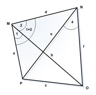
Figure 3: Braced Quadrilateral Adustment
In the figure there are four triangles. Compute all the 12 angles by using the cosine formula.
Step 5:- Computation of Latitude and Longitude
To find out the coordinates of unknown stations we must have Geodetic coordinates of one station. Geodetic azimuth of one base line connected to the known station.
OR
Geodetic coordinates of two stations.
Survey of India use Clark’s formula for precise determination of latitude and longitude. It gives 1ppm accuracy up to 150km. whereas mid latitude formula for topo. Triangulation gives 8ppm up to 40km.
Read related article: